
11th And 12th > Physics
ELECTROMAGNETIC INDUCTION MCQs
Total Questions : 15
| Page 1 of 2 pages
Answer: Option D. ->
Zero
:
D
:
D
Circular loop behaves as a magnetic dipole whose one surface will be N-pole and another will be S-pole. Therefore magnetic lines a force emerges from N will meet at S. Hence total magnetic flux through x-y plane is zero.
Question 2.
As shown in the figure, P and Q are two coaxial conducting loops separated by some distance. When the switch S is closed, a clockwise current Ip flows in P (as seen by E) and an induced current IQ1 flows in Q. The switch remains closed for a long time. When S is opened, a current IQ2 flows in Q. Then the directions of IQ1 and IQ2 (as seen by E) are 
Answer: Option D. ->
Respectively anticlockwise and clockwise
:
D
:
D
When switch S is closed magnetic field lines passing through Q increases in the direction from right to left. So, according to Lenz’s law induced current in Q i.e. IQ1 will flow in such a direction so that the magnetic field lines due to IQ2 passes from left to right through Q. This is possible when IQ1 flows in anticlockwise direction as seen by E. Opposite is the case when switch S is opened i.e. IQ2 will be clockwise as seen by E.
Question 3.
A coil of wire having finite inductance and resistance has a conducting ring placed coaxially within it. The coil is connected to a battery at time t = 0, so that a time-dependent current starts flowing through the coil. If I1 is the current induced in the ring, and B is the magnetic field at the axis of the coil due to I2, then as a function of time (t> 0), the product I2 (t) B(t)
Answer: Option D. ->
Passes through a maximum
:
D
:
D
Using k1,k2 etc, as different constants.
I1(t)=k1[1−e−tτ],B(t)=k2I1(t)
I2(t)=k3dB(t)dt=k4e−tτ
∴ l2(t)B(t)=k5[1−e−tτ][e−tτ]
This quantity is zero for t=0 and t=∞ and positive for other value of t. It must , therefore, pass through a maximum.

Answer: Option B. ->
i > 0.5 A
:
B
:
B
If resistance is constant (10Ω) then steady current in the circuit i=510=0.5A . But resistance is increasing it means current through the circuit start decreasing. Hence inductance comes in picture which induces a current in the circuit in the same direction of main current. So i > 0.5 A.
Answer: Option B. ->
The same
:
B
:
B
Power P=e2R; hence e=−(dϕdt) where ϕ =NBA
∴ e=−NA(dbdt) Also R ∝1r2
Where R = resistance, r = radius, l =Length
∴ P∝N2r2l⇒ P1P2=1

Answer: Option D. ->
B2oπ2r4R
:
D
:
D
P=e2R;e=−ddt(BA)=−Addt(Boe−t)=ABoe−t
⇒ P=1R(ABoe−t)2=A2B2oe−2tR
At the time of starting t = 0 so P=A2B2oR
⇒ P=(π r2)2B2oR=B2oπ2 r4R

Answer: Option C. ->
Jumps out of the core
:
C
:
C
When key k is pressed, current through the electromagnet start increasing i.e. flux linked with ring increases which produces repulsion effect.
Question 8.
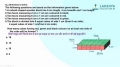
A rectangular loop with a sliding connector of length l = 1.0 m is situated in a uniform magnetic field B = 2T perpendicular to the plane of loop. Resistance of connector is r = 2
Ω. Two resistances of 6Ω and 3Ω are connected as shown in figure. The external force required to keep the connector moving with a constant velocity v = 2m/s is 

Answer: Option D. ->
10 H
:
D
:
D
e=B.dAdt=Ldidt⇒ 1× 510−3=L×(2−1)2× 10⁻³⇒ L=10H

Answer: Option D. ->
Induced current =1150A directed anti-clockwise if 5Ω resistor is pulled to the left with speed 0.5ms−1 and 10Ω resistor is held at rest
:
D
:
D
When 5Ω resistor is pulled left at 0.5 m/sec induced emf., in the said resistor
=e=vBl=0.5× 2× 0.1=0.1V
Resistor 10Ω is at rest so induced emf in it (e=vBl) be zero.
Now net emf., in the circuit=0.1V and Equivalent resistance of the circuit
R=15 Ω
Hence current i=0.115 amp=1150amp
And its direction will be anti-clockwise (according to Lenz's law)
Latest Videos


Latest Test Papers


Login With Google
Old way of Login
Login With Email